CIRC 2023 Summer Competition Tasks
Welcome to CIRC 2023! This competition is designed to challenge students to design, build, and operate a rover that can navigate and complete tasks on a simulated Martian surface alongside human settlement. These tasks are intended to be challenging and will require teams to use their problem-solving skills and technical knowledge to succeed. The following task descriptions and guidelines have been established to ensure a fair and safe competition for all participants. Please read through these descriptions carefully to make sure that your design suitable to the tasks at the competition.
Use the sidebar for navigation between the sections. For quick reference the tasks are also named below:
For information on the regulations of participating in CIRC, please see the 2023 Rules document.
Task Rubrics and Scoring
Tasks will be scored using a rubric which is available to all competitors. This may be useful for planning how to approach each task’s requirements and maximize scored points within the capabilities of the teams’ rovers.
Tasks are worth 100 points each, however Water Redirection is woth 150 points due to its extended length. Most tasks have bonus points available according to the rules, with exceptions to these bonues explained in the specific task descriptions below.
The 2023 Event Task Rubric can be viewed here.
Search & Rescue
Description
During the reconstruction of the settlement, a technician was tasked with repairing a failed reactor that suffered an explosion a year prior. While installing the last new uranium rod module, there was a containment leak on it, which resulted in the technician getting a blast of radiation. The technician was able to escape the immediate vicinity before collapsing.
Your mission, should you choose to accept it, is to safely bring the technician back to base, and to repair and restart the reactor.
This task will take place at night in the dark, and rovers should be prepared to be able to navigate with little natural light.
Documentation Provided
- Dimensions and STEP model of the Reactor Module that must be grabbed by the rover.
- The following Git repo contains more information, example code, and CAD Models: https://github.com/canspacetech/CIRC-2023-Night-Task-HW-SW
Requirements
Stage 1: The Rescue (20 Minutes)
- Your task is to locate the technician, and if possible, drag him back to base.
- The suit has a WIFI access point, that provides the gps location of the technician (2.4Ghz)
- By connecting to this device, you will be able to access a web page showing the technicians current location
- See Git repo above for more details
- The suit is also highly visible in the Infrared
- The suit also has a dosimeter that should be read as soon as possible and reported back.
- A readable image of the dosimeter will be sufficient
- Either as a JPEG or show the judge live on a video feed
- The technician is wearing a harness, with several possible attachment points
- Manual assistance to connect is possible, but with penalty
- Loop on a rope attached to technician also available
- Technician will weigh less than 5 kilograms
- Will not be a full-size human
- Expect a large plush “toy” with some attachments
- The suit has a WIFI access point, that provides the gps location of the technician (2.4Ghz)
- A further complication is that there is residual radioactive debris that must be avoided
- The locations of this debris is provided via GPS locations
- The debris is likely visible in the infrared
- It may be easier to move the debris instead of dragging the astronaut around it
- Astronaut should not come within 5 Meters of debris
- Once time is complete, team MUST move on immediately to stage 2
- The next team will be starting the task upon time completion.
- Two teams will be operating simultaneously, but in separate, adjacent play areas
- Teams will be starting with the Rescue task, then moving to the Power task.
Stage 2: The Power (20 Minutes)
- The reactor is close to functional, and just needs the faulty Uranium Rod Module (URM) identified and replaced before being able to initialize and start the reactor. The reactor has an identical GPS tracking system as the Technician. GPS is also known and can be provided.
- Three URM’s are required for the reactor to operate, and two are currently functional
- URM’s that are functional will emit significant infrared light
- Control panel may be able to indicate the faulty URM by initiating a Uranium Rod Module Test (button)
- Spare URM’s are located below the reactor control panel
- Properly inserted URM’s will have a green indicator light above
- Once installed, the Reactor Start (button) can be pressed to start the reactor
- Optionally pressing the Uranium Rod Module Test (button) will verify the URM’s are properly installed before starting
- Faulty URM should be recovered if possible
- Three URM’s are required for the reactor to operate, and two are currently functional
Autonomy bonus
- For both tasks, bonus points will be awarded for programmatically collecting the GPS location. (Scanning and connecting to the WIFI access point, gathering the GPS location)
- For both tasks, bonus points will be awarded for autonomously driving to and from each site (GPS location within 3 Meters)
Water Redirection
(We Got Pipes Like Bruno Mars)
Description
The transition to the new settlement has shifted the priorities of the colony and their water needs. This will involve redirecting the water from a Rodriguez well by disconnecting the existing pipeline and assembling a new pipeline to the water’s next destination. The urgency of this task requires two rover teams to perform this changeover. The materials for this project also need to be managed.
One team will be assigned the first 60 minutes to create a new pipeline and the other team will have 60 minutes to disconnect an existing pipeline. Once 60 minutes have elapsed, the teams will have 5 minutes to move their rover to the other side of the well and switch to the other task. Teams may perform minor intervention-level work during this period. The judges will use this time to reset the task as needed and notify the teams when the switch is complete.
Requirements
Disconnecting Existing Pipeline (60 minutes)
- Set the Rodwell’s pump to its purge setting and allow at least 15s for water to purge through the system. The pump can then be turned off (“O”).
- Close the ball valve.
- Turn off the boost station (“O”).
- Disconnect the pipeline components and move them to the staging area.
- Note that the last pipe and the ground inlet have a simple physical connection, not a marked zone.
- Plug the exposed inlet.
Note: This part of the task is much easier than the assembly stage, so this may be a good time to also manage the pipe inventory.
Connecting New Pipeline (60 minutes)
- Remove the plug from the ground inlet.
- Select a pipe in good condition and install by placing the end of the pipe against the marked zone on the well.
- Move the booster station into position, setting the marked zone against the first pipe.
- Install the second pipe.
- Note that the inlet has a physical connection, not a marked zone. The last pipe should be installed over the inlet first, then the second end of the pipe is pivoted into position against the marked zone of the booster.
- Open the ball valve and power on the pump (“I”). Set the pump to its pressurized setting and adjust the throttle to 50%.
- The throttle slider is very small and is located to the right of the pump setting switch.
- Turn on the booster (“I”).
- With the new pipeline now primed, adjust the throttle to 100%.
Pipe Inventory Management
Optional: no additional time granted
- Assess the pipes in the staging area and determine their respective condition: good, repair and scrap.
- Minor cracks can be repaired but severely damaged pipes must be scrapped. Miscategorized pipes will not count toward the score.
- Pipes identified with minor damage can either be repaired or documented for the next shift.
- Immediate Repair: Take a clear picture of the Crack Repair Procedure and submit it to the judges through Slack. This procedure will be located somewhere in the staging area. Follow the instructions in the document to fix the pipe. - Deferring the Repair: Take clear pictures of the damage and the pipe serial number. Send the images to the next shift (task judges) on Slack so they know what to look for. The images must be accompanied with a caption ascribing the condition to the serial number.
- Pipes identified with major damage should be logged so that new supplies are shipped to Mars.
- Take clear pictures of the damage and the pipe serial number. Send the images to Inventory Management back on Earth (task judges) via Slack. The images must be accompanied with a caption ascribing the condition to the serial number.
- Move the pipes to the appropriate areas. The areas are intuitively colour- coded.
Notes
Notes
- Major damage will be catastrophic and obvious that it can’t be repaired.
- The ball valve used is a ¼” unit like this.
- Rovers must be able to pick up and maneuver lengths of 3 inch diameter PVC pipe (3.25 inch OD), weighed down with additional components.
- The organizers reserve the right to change the rules and scoring for this task.
- Parking is limited to only vehicles carrying equipment to the task.
Traversal+
Description
Following the disastrous reactor explosion of 2022 your rover must traverse through the wreckage and identify valuable supplies to use in rebuilding the base.
Requirements
- Rovers must travel to different locations and identify the supplies left there.
- Supplies will be marked with an Aruco marker and a human readable marker.
- More points will be awarded for correctly identifying the Aruco marker.
- The markers will be on the top surface of the supplies.
- Some supplies will be at GPS locations and some will need to be found with alternative wayfinding techniques.
- The supplies may come in different sizes and shapes. They will all be on the ground.
- Your rover does not need to pick-up or interact with the supplies other than reading the markers.
- Supplies will be marked with an Aruco marker and a human readable marker.
- There are 7 locations.
- 4 locations will have GPS coordinates.
- The first 2 locations must be visited in order.
- The following locations can be visited in any order after successfully reaching the second location.
- One location will be a certain distance and compass heading from the second location.
- The distance and heading will be clearly marked on a sign at the second location in a human readable format.
- The compass heading will be displayed in magnetic heading.
- The distance will be displayed in meters.
- A location will have a light beacon. The rover must scan the terrain for the light and navigate towards it.
- The light will be at least 50 cm above the ground.
- The light will have a consistent strobe pattern.
- The light will be amber in colour.
- The light will emit in 360°.
- A sample video of the light beacon strobe pattern in sunlight is available here
- A location will have a radio beacon.
- The Beacon is a BLE Beacon (Bluetooth Low Energy) broadcasting as “CIRC BLE Beacon” with an omnidirectional antenna (Vertical Polarized) on 2.4GHz
- The Beacon is common to the Search & Rescue task, see https://github.com/canspacetech/CIRC-2023-Night-Task-HW-SW for more details and examples.
- Other GPS locations will be more difficult to reach and may involve obstacle avoidance and may not be within line of sight of the antenna location.
- The GPS coordinates will be provided during setup time. The start location is not a GPS coordinate.
- Reaching the locations may involve traversing difficult terrain and avoiding obstacles.
- Extra points will be awarded to teams who can reach a location autonomously.
- To get full points for finding the supplies at a location, the rover must move to within 3m of the location as measured by a judge and be able to see the human readable marker or the Aruco marker on a rover camera or sensor. This should be visible to the judge at the base station to be awarded full points.
- Some points will be awarded if the camera is manually aimed at the marker and the rover autonomously identifies the code. More points will be awarded if the rover autonomously scans for the marker and identifies the code.
- Full points will be awarded if the Aruco scanning and detection software is running in the background and automatically displays the correct result when the Aruco marker comes within range and frame of the camera.
Land Speculation & Prospecting
Description
Following the loss of Site 1 to reactor malfunction in 2022, the decision has been made to establish secondary outposts away from the main base to allow continuity of operations in the event of further disaster. Your rover has been dispatched to a possible site to carry out exploration and surveying work.
Teams must investigate the promising area and evaluate it for further development according to the included list of metrics. A location for each of the planned structures must be selected. Record your survey route and note any landmarks or potential navigational hazards to facilitate the development of the area and lay the groundwork for further scientific studies.
Soil samples should be retrieved and analyzed both for scientific study and as the first step of the post-construction environmental impact assessment. After the return of their rover, teams will have a short time to analyze their sample and compile a report on their findings and recommendations before the complex must be evacuated.
A map of the area will be provided prior to the competition.
Settlement
Three structures are planned for the outpost:
The research station is a 15.0 meter by 7.5 meter structure that will house the astronauts and their equipment and serve as a home base for operations in the area. A large area of stable ground is needed to support such a structure. Provisions for power generation and movement to and from this structure should be considered.
The vehicle hangar is used to store and maintain buggies and rovers. The hangar is composed of modular bays 6 meters long and 4 meters wide which can be joined on the 6 meter walls to create a larger structure. Each bay has a capacity of one buggy or two rovers. At minimum, two bays will be required for the outpost, with additional bays being desirable.
The communications dish allows the outpost to connect to the satellite network. The available communication satellites are in a low-inclination orbit, therefore the dish must have line of sight to the southern sky to maintain a connection. The planned dish is 4 meters in diameter and the bottom is 1 meter off the ground in its standard orientation. The base of the dish requires a 3 meter by 3 meter area.
Additionally, the outpost should have an open area to receive cargo landers. The landers have a footprint of 4 meters by 4 meters and can take off and land vertically. Additional space on all sides of the landing area is recommended and the area must be at least 30 meters from other structures as a safety measure.
Site Metrics
- Available Space:
- Habitation Complex
- Vehicle Hangar
- Communications Dish
- Landing Field
- Nearby Resources:
- Mineral Resources:
- Metal ore
- Carbonaceous materials
- Soil Composition
- Water content
- Nutrients
- Scientific Potential
- Signs of life
- Geological interest
- Mineral Resources:
- Development Potential:
- Easy route to chosen site
- Terrain suitable for building
- Shelter from inclement weather
Requirements
Exploration
- Explore the area and select a site for each of the planned structures. The following actions must be undertaken during the survey:
- Record the route taken using GPS waypoints.
- Document and photograph any landmarks or navigational hazards in the area. Estimate their location relative to your route.
- At each site:
- Record the GPS coordinates of the extents of the chosen site, i.e. record the GPS coordinates such that the site can be represented on the map by a polygon with vertices at the coordinates.
- Take a panorama photograph of the site. A minimum of 180o is required, with 360o required for full points. Select a point with good visibility somewhere within the previously recorded extents. Record the GPS coordinates of the point at which the panorama was taken.
- Take photographs documenting the site’s major features and compliance (or lack thereof) with the above metrics.
- Collect a 5 - 100 g soil sample for further study. The test must not deposit any foreign materials in the test area. Samples must be kept separate from one another.
- Return to the starting point with all samples.
Report
- Following completion of the rover’s time on the task site, teams will have three hours (starting either when the team leaves the site or when the team’s task time is up, whichever comes first) to perform additional tests on the sample, and write and submit a report of up to 3500 words (excluding references, if present) on their execution of the task and their findings. Reports should be submitted to the judges via the Slack workspace dedicated to the event. No reports will be accepted after three hours. The report must include:
- Abstract:
- Summarize the situation and the purpose of the report, and provide a high-level overview of the procedure and findings.
- Search procedure and route:
- Provide an explanation of the approach to the survey used by the team. Justify the areas investigated and the route taken.
- Show a map of the search area. Indicate on the map the route taken by the rover, the extents of each site, and the locations of any landmarks, navigational hazards, or other features of interest spotted during the survey.
- Report on sites:
- State the GPS coordinates recorded at each site.
- Show the panorama photograph of each site and the GPS coordinates at which they were taken. Indicate the direction from which the site was approached and comment on any visible landmarks.
- State the observations at each site. Show the photos taken during the survey and explain their significance.
- Describe the sample collected. Justify the location from which it was collected.
- Explain the methodology of the tests carried out on the sample.
- Describe the results of the tests on the sample and their significance.
- Describe the route to the selected site. Describe and comment on the non-site-related features noted during the survey.
- Analysis:
- State your recommendations for the development of the area. Address each site and any other observations from the survey. Justify your recommendation using the evidence and observations described elsewhere in the report.
- Make suggestions for long-term development (if applicable). These suggestions could include both engineering goals (e.g. development of mineral resources or construction of additional facilities) and scientific studies (e.g. preservation of geologically interesting region or a plan to collect a range of core samples) at the site.
- Abstract:
Judge’s Commentary
- When writing up your report, please consider the outline of how scientific reports/papers are typically written:
- Abstract
- Introduction
- Methods and Materials
- Results (sometimes includes discussion)
- Discussion
- Conclusion
- Please be sure to include your team name in the document name
- Teams are free to select multiple sites in close proximity to one another, but will be required to justify how the sites were differentiated (e.g. separated by physical feature of the area, must be approached via different routes, etc.) in their report to receive full points for identifying multiple sites.
- Take care when rounding GPS coordinates. Rounding to three decimal places has introduced errors of up to 40 meters in previous events.
- Consider multiple possibilities when formulating your approach and recommendations.
- Teams are strongly encouraged to submit their report even if they cannot complete the field task. Points will be awarded for all sections of the report that can be completed without data from the field (e.g. the intended exploration route, any observations that could be made from the rover, the intended experiments, recommendations for further study, etc).
- Similarly, consider starting the report ahead of time. Aspects that are not dependent on your results and can be completed in advance to free up time before the deadline. Establishing an outline and skeleton can also save time for writing up your results.
- Tell the story of the investigation and tests. Link your various sections together.
- All metrics, even those that are not met, should be addressed when describing and comparing the sites.
- The “why” and “how” are as valuable as the “what” in reports. In addition to describing observations, experiments, or decisions, provide an explanation of their meaning.
- Differentiate between what your plan was and what you were able to accomplish.
- Be honest about technical difficulties when writing the report. Acknowledge when things didn’t work. If something went wrong with your rover that prevented you from completing the task, please provide a brief explanation of what went wrong
- Clearly state what is fact and what is speculation in your report. For example, describing the site as “rich in ironstone” would be accurate only if a sample of the rock was obtained and tested or closely examined by an expert. If this was not done, a team should simply provide a physical description of the rocks, and may add that it resembles ironstone.
- Similarly, reports should differentiate between observations that can indicate some features and those that necessitate it. For example, water is a necessary precondition to life as we know it. Thus, identifiable life suggests the presence of water, but the presence of water does not necessarily indicate the presence of life.
- Any assumptions made in the report must be stated explicitly.
- Remember that this is supposed to be on Mars, so plants won’t grow outside of a climate controlled greenhouse or other suitable growing chamber.
- Similarly, ignore infrastructure surrounding or intersecting the task sites.
- Figures must be described in full, either through a descriptive caption or references in the text. Figures without proper description are not useful.
- Note that it’s a rover competition, and only observations and data acquired from on board the rover will be awarded points in the field section. The science portion can of course be recorded by any convenient means.
- In the event of technical difficulties, other pictures may be used to provide clarity, but will not be considered for observation requirements, only explanation requirements.
- Good spelling and grammar are appreciated. If there’s no time to proofread, run the document through the spelling/grammar check before submitting. No penalties are applied, but a well-presented report is more enjoyable to read, and seems more compelling in its arguments.
Arm Dexterity
Description
The new settlement needs a reliable power source. New components are on the way, but it will take months or even years to arrive. Spares and parts of the old power source have been salvaged, and luckily there appear to be enough components to configure a new system. These panels were originally designed for human operation, however, due to the earlier damage, it is no longer safe for humans to manipulate the controls. It is up to your team to use their rover to complete the task and configure the system to get power for the settlement back online.
Requirements
- Complete all phases of the task by following steps in the instruction manual and instructions given by either the System Monitor Panel display or System Monitor Panel diagnostic port to return all 4 power control panels to operational status.
- Confirm all panels are operational by interpreting the control panel readouts and displayed information or by optionally reading the System Monitor Panel diagnostic port data.
- Avoid damage to the panels from using excessive force with the controls. Impacts and other movement greater than approximately 2G acceleration or 100N force will trigger sensors which will initiate a safety shutdown.
Documentation Provided
- The engineering team is still planning the new power source. Documentation will be made available when ready. Teams should expect the following items before the event:
- Dimensioned diagrams (PDF) (DWG) of the control panels
- Example of how to optionally interface with the diagnostic serial port on the System Monitor Panel. The diagnostic port may be used to download status reports, instructions, and use the onboard diagnostics to bypass steps. For electrical information see the Notes below.
- Instruction manual explaining how to initiate each phase of the task and interpret status lights. Note that complete instructions will be shown on the System Monitor Panel display during the task and this manual will also be available on paper during the task.
- Diagram of provided tools found by the salvage team.
Tools Provided
- Simple tools to manipulate buttons as required. See documentation for information.
Notes
- General:
- The rover must be able to move between all 4 control panels to complete the task.
- Panels will be separated by at least 1m. The rover must be able to traverse relatively smooth and level terrain between panels.
- Controls will be located at heights between 0.3m and 1m above the ground. Detailed positions will be shown in the documentation.
- Some controls may require tools to operate. For example, some steps may require two buttons to be pressed at once or may require a safety guard to be lifted. In order to facilitate this for most rovers, simple tools will be provided on the ground at the starting area which may be picked up by the rover. Teams are welcome to bring their own, but these will be counted towards the weight of the rover.
- All panels have an accelerometer which will reset the panel if excessive movement greater than approximately 2g or 100N force is measured.
- System Monitor Panel (Part of the Fuel Control Panel)
- A 200x100mm display to show the current system status and provide instructions for proper operation of the other panels.
- 2 buttons for menu interaction with the display.
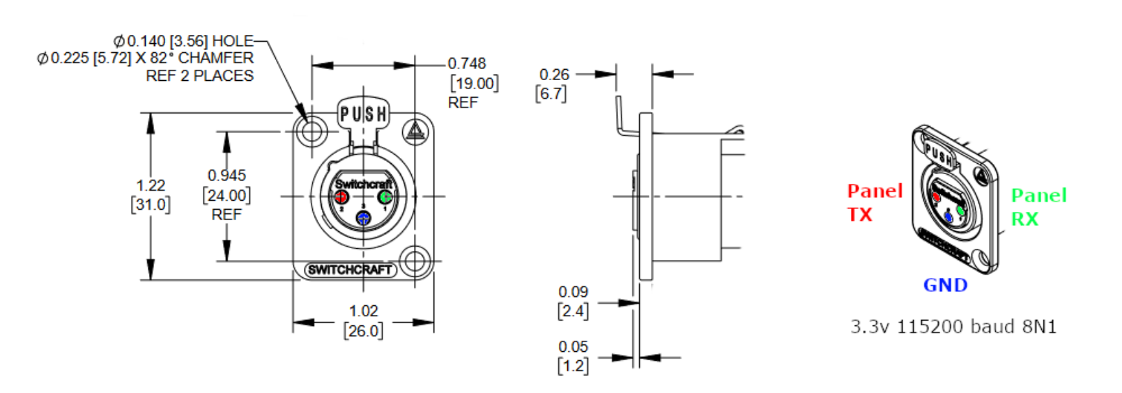
- 3.3V TTL serial Diagnostic Port (115200 bps 8N1) on a 3 pin female connector. Note: this connector is the common “XLR” type found in audio equipment.
- The diagnostic port on the System Monitor Panel will allow the teams to bypass some steps or read diagnostic information more quickly than the display or other status lights.
- Teams may use a cable or create a wireless device to stay connected to the diagnostic port as they work on other panels.
- The port does not supply power.
- The connector has a latch which can be disconnected by pushing a tab. Disconnecting from the receptacle will not be required to complete the task, but completing the task with all equipment returned to a clean state is worth a small amount of points. See the overall task rubrics for information.
- Startup Panel
- 9 pushbuttons in a grid, with status lights.
- This panel was designed to be operated by a human, and will require pressing multiple buttons simultaneously. This may optionally be completed by using the provided tool.
- Instructions to correctly manipulate the panel will be provided on the System Monitor Panel display.
- Fuel Control Panel
- 4 ON-OFF Toggle Switches with status lights
- 15 pushbuttons arranged in a triangle with status lights.
- Instructions to correctly manipulate the panel will be provided on the System Monitor Panel display.
- Performance Tuning Panel
- Joystick with status light
- Rotary Switch with status lights arranged in a circle around the panel
- Pushbutton with status light
- Instructions to correctly manipulate the panel will be provided on the System Monitor Panel display.
Autonomy Points
- Autonomy points will be awarded for automatic completion of individual steps within the task. These steps will be noted in the task rubric. It is not expected to complete the entire task autonomously from start to finish.
- There will be 3 attempts at autonomy points allowed.
- To be eligible for autonomy points, teams must navigate to and manipulate panels (e.g. press buttons) without manually positioning the robot or the robotic arm. For example, a team may use computer vision to identify and press buttons or more simply execute pre-programmed movements.
- The team must inform the task judge when they will attempt autonomously interacting with the panels.
- No points will be awarded if the rover must be manually positioned to interact with the panel. The task judge can clarify if they feel the rover has been positioned in a way that invalidates the autonomy attempt. Also note, an intervention may not be used to position the rover anywhere except the starting position.
- No points will be awarded for unnecessary steps, such as pressing buttons that are not required for that phase of the task.
- Refer to the provided documentation including diagrams with positions of buttons and controls for planning autonomous steps.